How to make AZ-Nunchuk
Items needed
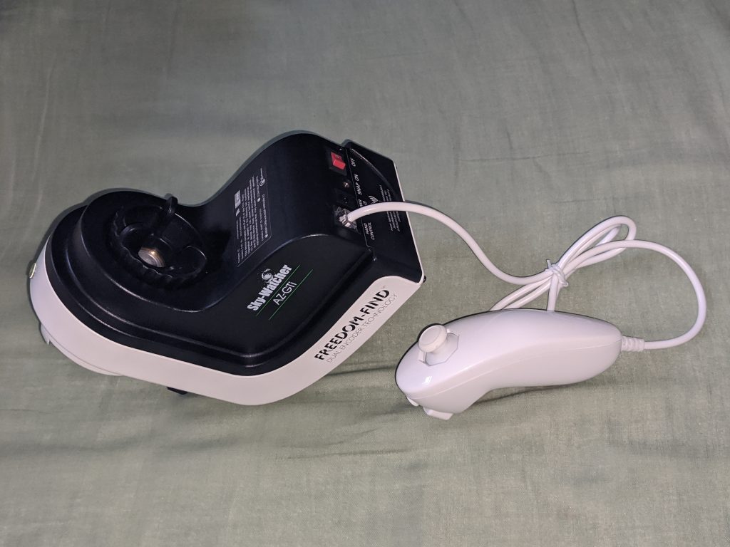
Nintendo Wii Nunchuk
arduino pro mini board or compatible clone
There are two versions of Arduino pro mini, 3.3V 8MHz and 5V 16MHz. 3.3V is preferble because both serial commucation to AZ GTi and power surpply for Nunchuk are 3.3V. However both of them are also 5V compatible so 5V version works perfectly.
Piezo buzzer without circuit. With wire. Diameter should be less than 20mm.
RJ12 6P4C moduler plug.
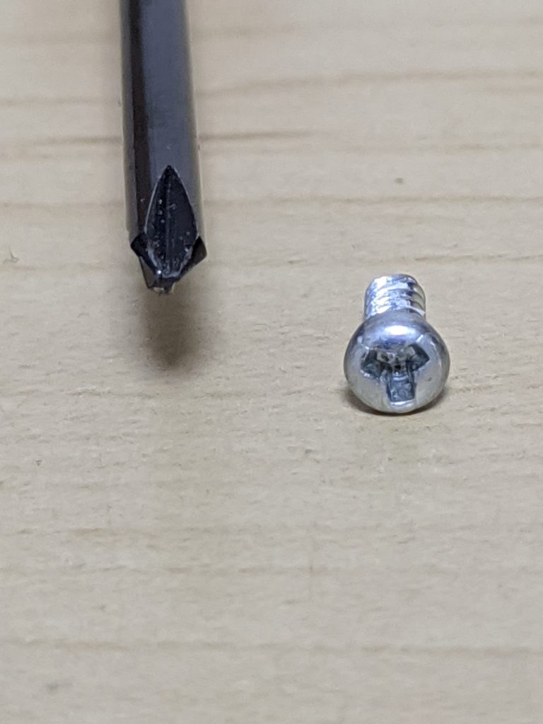
Y-shape special driver, to open Nunchuk
Solder and Solder Iron
Moduler cable cramper tool
Write sketch to Arduino
I uploaded sketch here. (Updated on 2025/Feb/8 for AZ-GTi latest firmware)
github.com/naokiueda/az-nunchuk
This is far from “elegant codes” those are often seen in github. However, I upload code which is working. I may clean and align code and upload better code in future, though.
You may need to install “Float64” library to compile.
You can download zip file from
https://github.com/mmoller2k/Float64
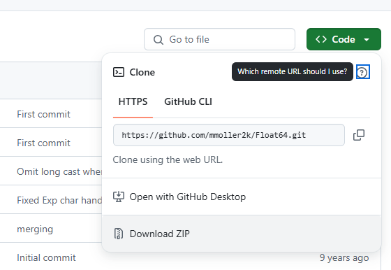
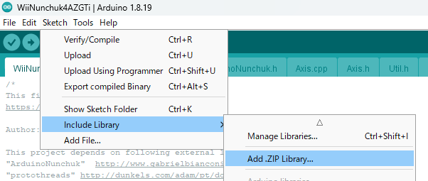
Then in Arduino tool, “Sketch” menu -> “Include Library” -> “Add .ZIP Library”, and select downloaded file.
Write Sketch to “Arduino Pro Mini” need USB-Serial board.
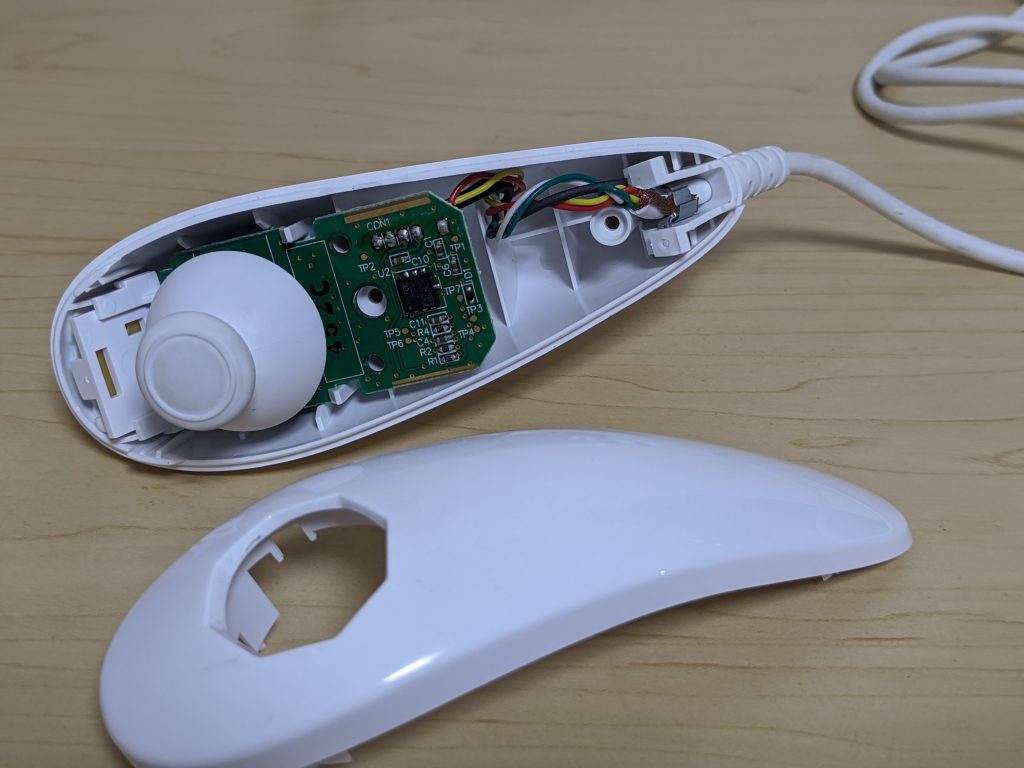
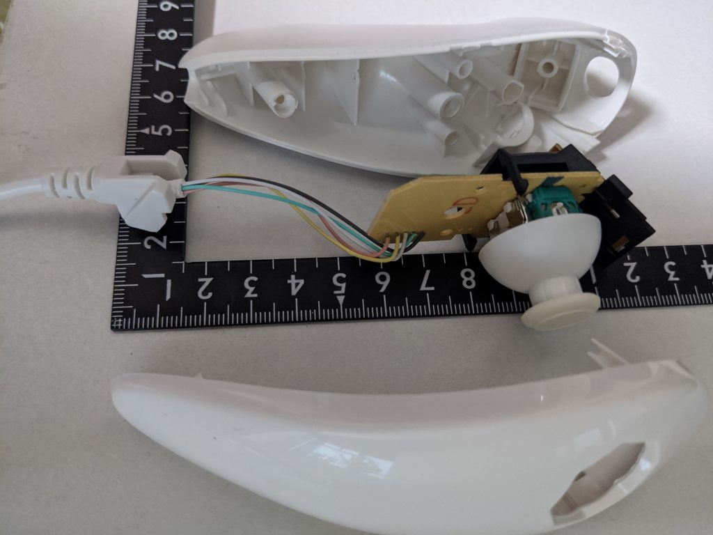
Dissolve Nunchuk
Nintendo wii nunchuk use Y-shape screw, and you need special driver for it.
You need to use RJ11/RJ12-6P6C/6P4C moduler plug. You may use 6P4C moduler cable, but I recommend to use soft cable. Round type moduler cable has strong (hard) wire inside, and it will be difficult put them inside Nunchuk body.
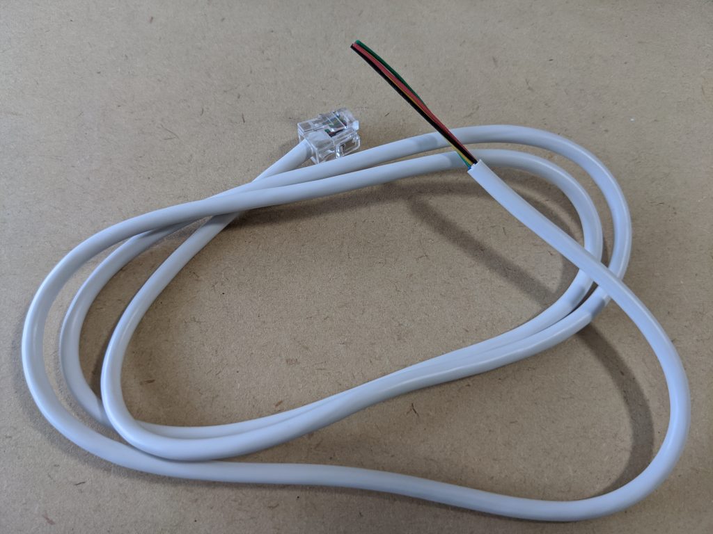
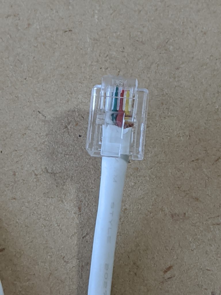
In this page, I don’t use moduler cable. In stead, I cut Wii-Connector from original Nunchuk cable, and replace it with 6P4C moduler plug. Wii-Nunchuk’s original cable are soft and flexible because they must be designed to gaming purpose.
Cut Wii-connector and peel about 6mm(=1/4 inches). Cut shield cupper wires.
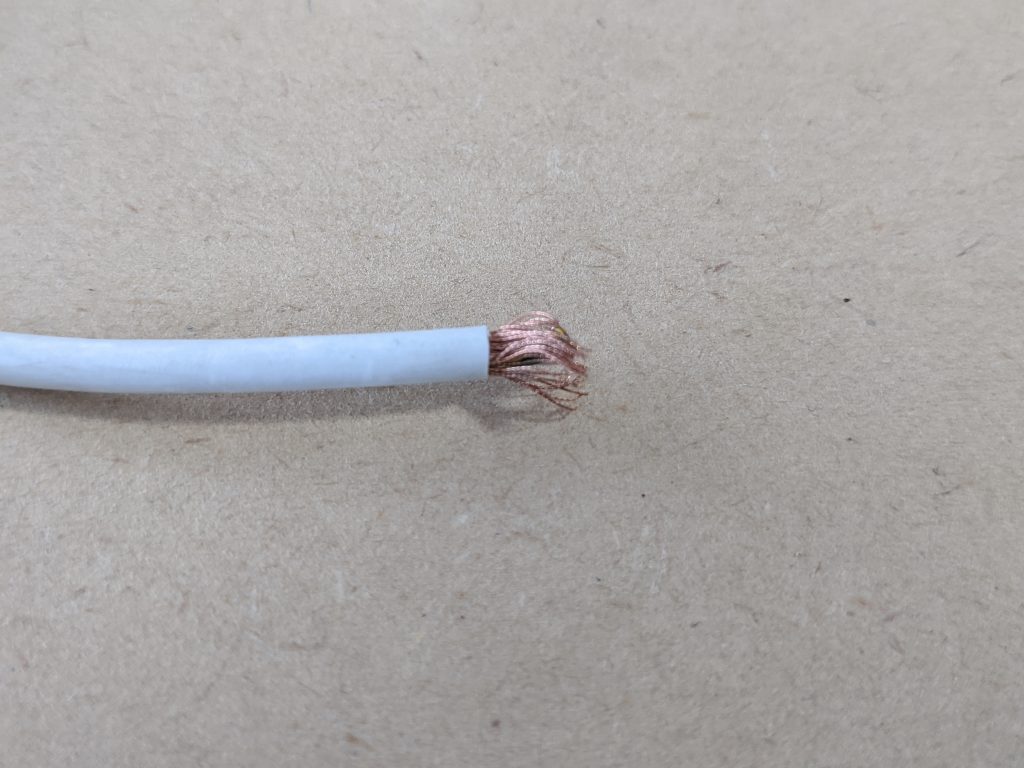
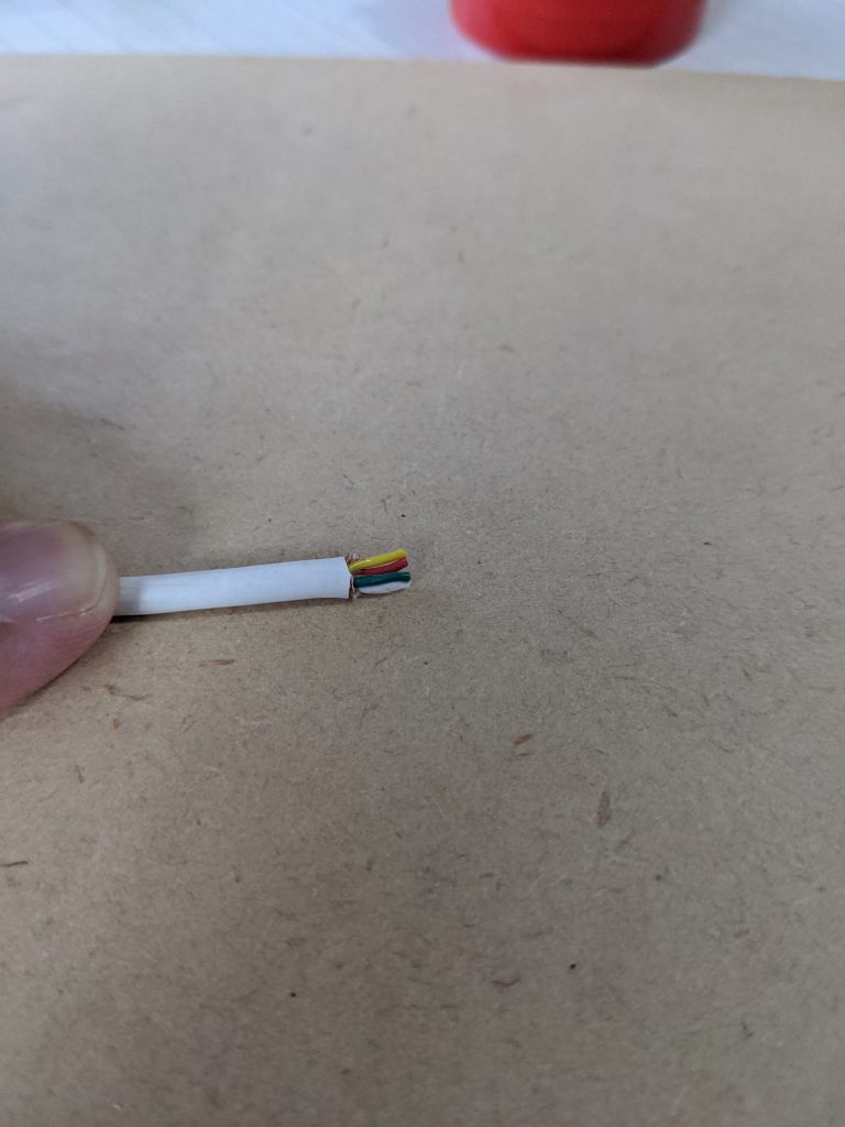
There are 5 wires, Red, Black, Yellow, Green, and White. But cable does not have Black (Black is connected to Shield wire), and only has 4 wires.
Allign these 4 wires, as straight ans parallel as possible.
I recommend align in order of following for convenience in later process.
Yellow
Red
Green
White
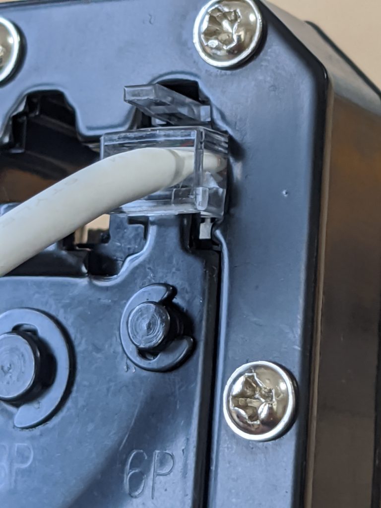
Insert these wires into 6P4C plug, and Crimp it with Crimp tool.
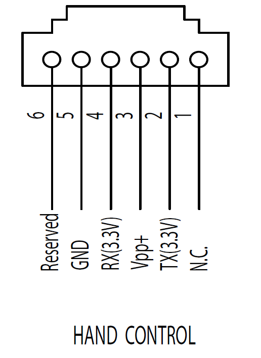
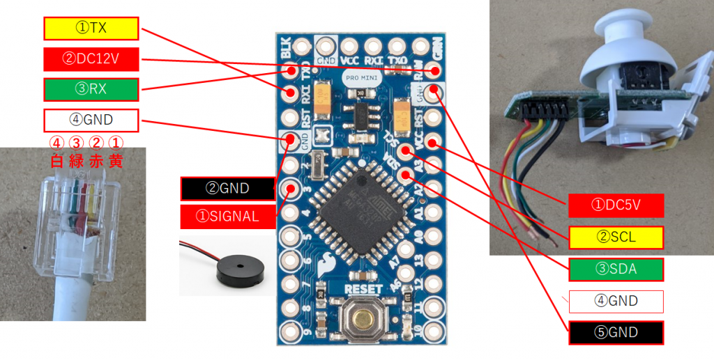
Yellow (AZ GTi)Tx
Red DC12V
Green (AZ GTi)Rx
White Gnd
If you use non-authentic Nunchuk, cable color may differ.
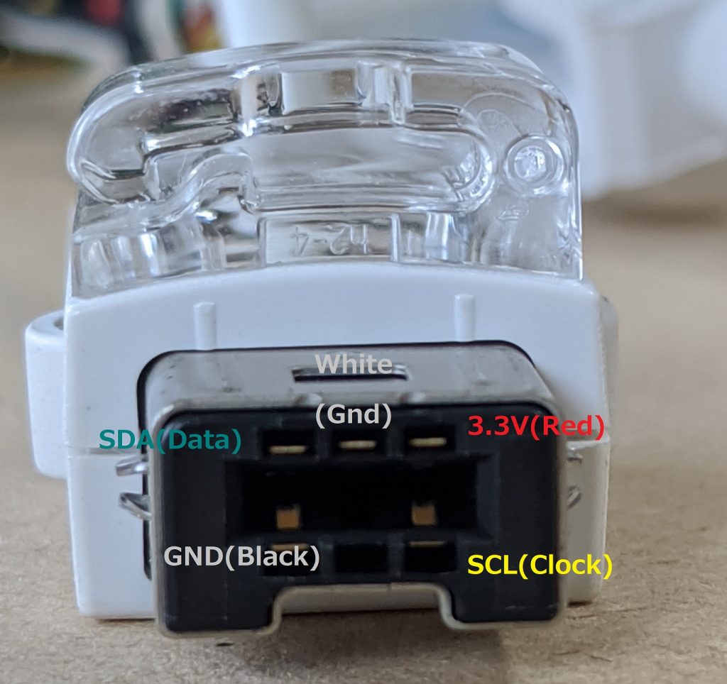
AZ GTi Hand controller has following pin assign.
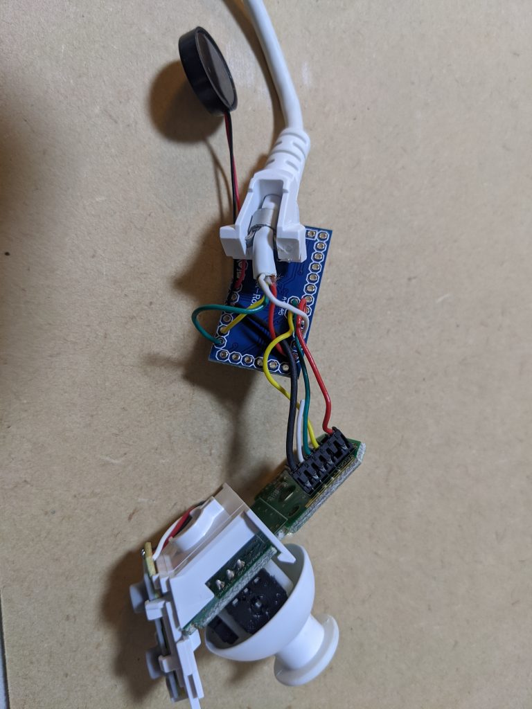
Remove wire and board from body.
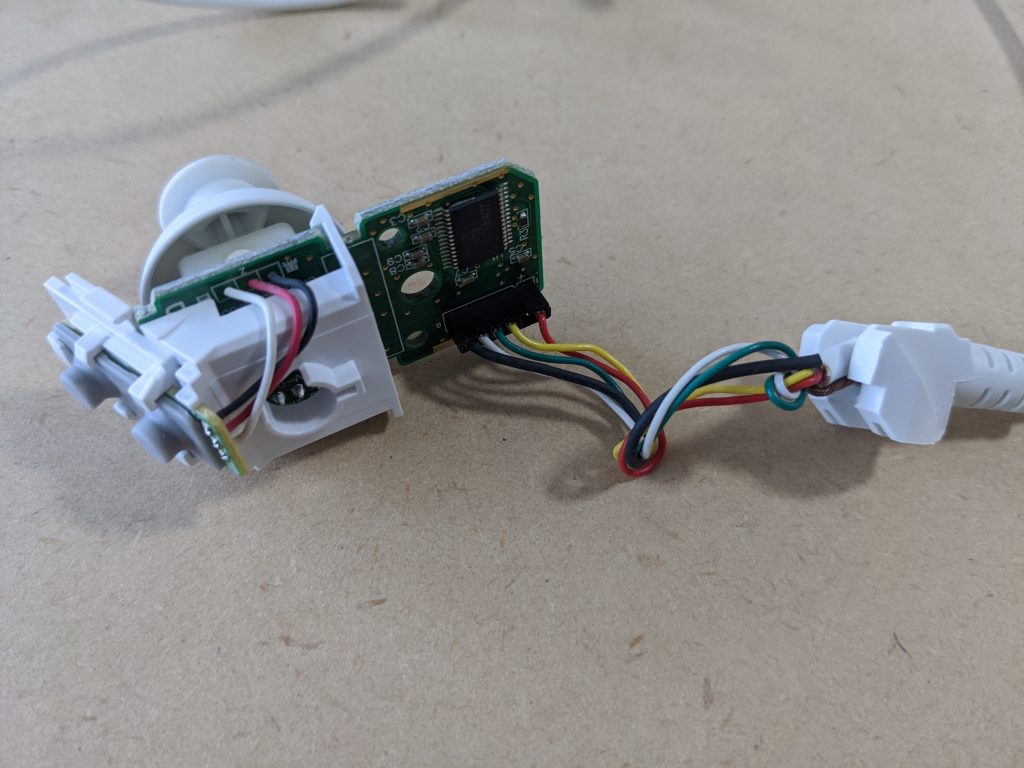
Caution: Cut wire about half and half.
If one side is too short, Arduino may not fit inside body.
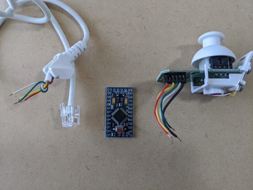
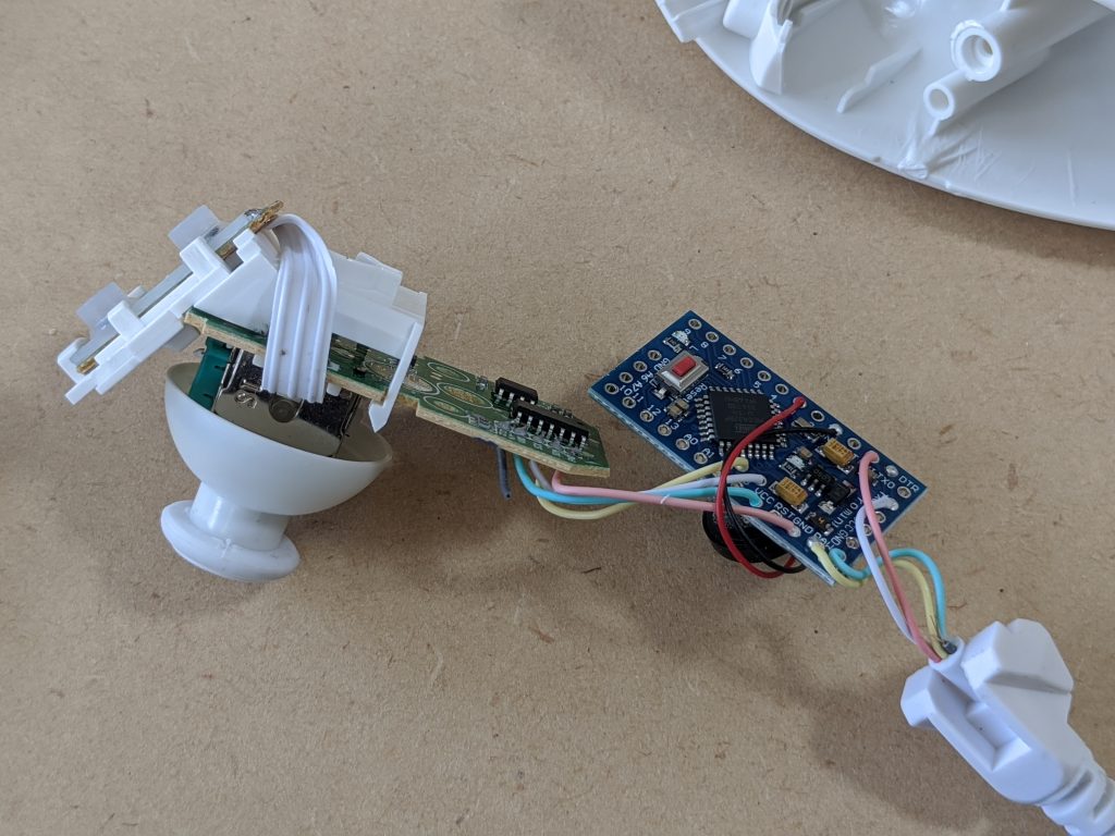
Solder wires directly on Arduino board. If you use pin-header, it may not be fit inside body.
Solder wires as following
In the sketch(Arduinot program), I assign buzzer to pin-3.
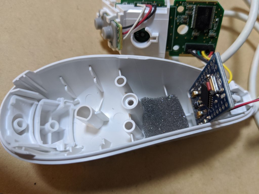
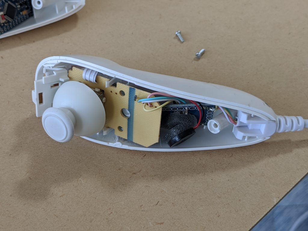
To avoid clatter sound, use anti-burn sponge to fix arduino.
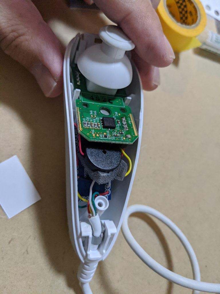
Set cable boots, arduino, then place Nunchuk board.
Also use sponge to fix buzzer.
Set top cover and screw it.
In case if you use compatible clone Nunchuk
I bought several types of clone nunchuk. Most of them has shorter wire inside, and that makes “fitting”, – put arduino inside body- , difficult.
Also, wire color may vary, so you need to confirm which wire has which pin, SCL, SDA, 3.3vDC, and Ground BEFORE you cur wires.
This is AZ-Nunchuk modified on clone Nunchuk
This is AZ-Nunchuk modified on clone Nunchuk
Sell it?
Unfortunately, I can’t sell it. I can’t sell someone’s (Nintendo Corporation)product with my modification. That violate their intellectual property. However, you can buy NUnchuk and modify by yourself for your usage.
Therefore, I opened my arduino program and how to make it.
Please enjoy your electronics work.
About Usability
About Usability
It is very convenient because I made what I want.
Especially in EQ mode, AZ Nunchuk take care of tracking, so I do not need to use not even connect SyncScanApp at all.
I only use SyncScanApp when I want to use GOTO functionality.
Known Issue
SyncScanApp use Motor Protcol. AZ Nunchuk also use Motor Protcol. ANd AZ GTi looks only handling with one of them at the same time.
In some case, sending command from both may cause motor hang-up, and you need to power-off and on again. (And Alignment, too)
Especially, when SyncScanApp is
– in tracking in Alt/Az mode
– in displaying information, such as Ra,Dec,Position, etc., real time
SyncScanApp is keep sending command every second. In this case, using AZ Nunchuk may cause hangup.
So when you Operate AZ Nunchuk, please keep following in mind, so you can use it without trouble.
– Disable “Tracking” in SyncScanApp
– Do not display “Info” in SyncScanApp
– Do not use move button in SyncScanApp and Nnnchuk at the same time
- Do not operate Nunchuk white “GOTO” movement
Thanks so much for your great works!
I am currently making a STM32 to to USB joystick for my Az-Gti following FreeJoy
(https://github.com/FreeJoy-Team/FreeJoyWiki) and through INDI lib (https://www.indilib.org/controllers/joysticks.html).
It works great, but I admire your solution which is more simple and do not require an SBC for control.
I would also like to directly connect the STM32 FreeJoy through UART interfaces on board to Az-Gti port.
However, I do not know what command should be sent to the mount as the protocol sound like mystery to me.
Could you please shade some light in the communication protocol through serial port such that I could try to implement this function for my customized controller? By the way, I would also like to add an ST-4 port to my mount to maximum its capacity!~
Vasco
Thank you for your comment.
SkyWatcher Motor Protcol documentaion is here.
https://inter-static.skywatcher.com/downloads/skywatcher_motor_controller_command_set.pdf
When start conversation to mount, you need to get two values, “CPR” and “TMR_Freq”.
These value are needed to calculate “T1” value that control speed.
Then you set “Motion Mode” (Moving Direction, etc), “T1 value”(Speed), Then send “Start”.
Cautions:
Before you start motor, send “Inquire Status” commend and get status, and make sure motor is not busy.
Also, when you are in fast moving, or change moving direction, send “Stop” once and monitoring until stopped, then send moving command.
P.S.
About ST4 port for AZ GTi, I’m currently working on it. 🙂
Thank you very much, I was looking for a solution that would help me build something similar, and here I found everything done, and very well done. I have it done, working and happy. I only had some problem with the libraries (I had to download Float64-master and pt-1.4 as well) but once that was solved it worked the first time and the experience is very pleasant, I am looking forward to trying it with the stars (these days it is cloudy) many thanks again, (with each passing day I think better of Japanese people ;-).
I think this is among the most important information for me.
And i am glad reading your article. But want to remark on few general things,
The site style is perfect,
the articles is really excellent
: D. Good job, cheers
thanks, very interesting 🙂
Очень интересная информация. А мне давно хотелось попробовать найти металлоискателем интересные находки. Не хотелось покупать очень дорогой прибор, так как я новичек в этом, заказал вот такой простенький и недорогой http://alii.pub/5xkqnd . В моей коллекции уже несколько монеток и крестик 🙂
Super idee und tolle arbeit.
ich bekomme ein fehler beim kompilieren
C:\Users\mein\Documents\Arduino\libraries\pt-1.4\example-codelock.c:59:10: fatal error: sys/time.h: No such file or directory
Mehrere Bibliotheken wurden für “pt.h” gefunden
#include
Benutzt: C:\Users\mein\Documents\Arduino\libraries\pt-1.4
komm nicht mehr weiter.
gibt es eine lösung?
besten dank
Hello kimbu
Thank you for comment.
It need “Protothreads” library.
My library path is “C:\Users\*\Documents\Arduino\libraries\Protothreads“, and not “C:\Users\*\Documents\Arduino\libraries\pt-1.4”
Please try to install Protothreads library by following menu.
Tool–>Manage Libraries, then search for “Protothreads”, and install.
Best Regards
Naoki
Danke für die Rückmeldung
Hat funktioniert
Hab wieder ein Problem der nunchuk der untere Bauteile wird heiss und kein hinaus dem buzzer.
Nachdem ich die 12 volt getrennt und 5volt extern angeschlossen habe kommen die Töne aber kann nichtvgesteuert werden?
Kinbu
>der untere Bauteile wird heiss
Is your Arduino-Pro-Mini genuine or clone?
If it is clone, power supply IC may be maximum 12V DC.
8 batteries = 1.5V * 8 = 12V. However, new battery sometimes be around 1.7V. Then the voltage come from AZGTi is near 13V or 14V, then, the power supply IC on Arduino-Pro-Mini-clone is broken.
Genuine Arduino-Pro-Mini has power supply IC that is maximum 20V, and safe for very new batteries.
Please check this first.
先ほどAZヌンチャクを作成しようと途中経過をお伝えしたものです。
組み立てまして操作したところ、無事動き出しました。
大事に天体導入時に使いたいと思います、ありがとうございました。ご報告まで。
ご報告、どうもありがとうございます。
大変うれしいです!
Hello! I have just built this amazing project 🙂 Unfortunately it is not working correctly 🙁 When the nunchuk is plugged in and I turn on the az-gti I hear the beeps either ascending or descending. Each time it turn on and off again, it goes the opposite direction, as if the C button is permanently pressed. But I have checked the button circuit and it seems fine (it is not permanently closed). I have also verified all other wires and everything seems correctly connected. I also checked all the boards for any solder connection issues and it seems fine. I have a clone nunchuk and a clone arduino. Perhaps the nunchuck is faulty?
Have you ever experienced anything like this? Thank you!
Hello. Thank you for preparing the project. I am trying to use it with my Star Adventurer GTI, but after connecting it nothing happens, and after about 20 seconds I hear an intermittent signal from the buzzer. When I connect the board to the computer, I see the command “:e1” in the console.
I have checked that the Nunchuk and the board itself are working correctly, and the only issue I have is with the serial connection to the mount head.
Could you please explain what the correct wiring/connection should be to the mount with the 8-pin controller connector (RJ45)?
kbrelins
Thank you for your message.
I haven’t test with Star Adventure GTI.
But I could found pin assign of SkyWatcher RJ45 connector like this:
https://www.cloudynights.com/forums/topic/923311-heq5-rj45-pinout-eqmod-wifi-bt-adapter/
By the way, is your Nunchuk work correctly with AZ-GTi?
If so, and if you got source code from my Girhub before 2025/Feb/8th, please take new one.
I made some fix on Feb to adopt SkyWatcher’s new firmware. My old code needs to be updated.
Best Regards
Naoki
Hello again. I checked the pinout of the connector in my mount once more and it matches the one you provided (RJ45). I also confirmed that the connection through the UART converter with the SynScan Pro app works. The converter itself (328p) with the Nunchuk works properly as well – I can change the hemisphere and azimuth (I can hear the responses from the buzzer). However, no connection with the mount occurs. In the terminal I only see “:e1”, and after several attempts I get “TimeOut”.